|
| |
| |
>> Download this
document (PDF approx. 1.4M)
|
CODAR
OCEAN SENSORS
SeaSonde® Remote Unit System Specifications
Product Code: SSRS-100
SeaSonde Remote Unit Components†
•
1 Transmit Antenna Assembly (SSTA) & 1 Receiver Antenna Assembly
(SSRA) OR,
1 Combined Transmit-Receive Antenna Assembly (SSTR) (avail.
for frequencies 11.5 MHz and higher)
•
1 Transmit Cable & 1 Receive Antenna Cable Set OR,
1 Combined Transmit-Receive Antenna Cable Set (avail. for frequencies
11.5 MHz and higher)
• 1 SeaSonde Receiver Chassis (SSRX)
• 1 SeaSonde Transmitter Chassis (SSTX)
• 1 Radial Site Data Acquisition System (SSDA 100)
• 1 Electronics Interconnector Cable Kit
• 1 Set Operator Instruction Manuals, PDF format
•
One Year Manufacturer’s Warranty
† Base components only: review Remote Unit
Configuration Options inside this specification sheet.
| Technical
Specifications |
Radiated Signal Specifications
Operators must adhere to local radiated signal regulations
and receive proper authorizations prior to operation. Licenses
should be obtained by system operator/owner prior to
transmission. System can be manufactured to be tuned for
operation at user-specified frequency, which can be one of
the authorized oceanographic radar bands as defined by ITU,
or any other band authorized by presiding local authority.
Transmitted signals are within the latest ITU guidelines for
oceanographic HF radar.
Output Radiated Power:
80 W peak, 40 W average
Operating Frequency Range:
Electronics: 4.4 – 50 MHz
(select specific frequency
for filter tuning)
Antennas: Select a frequency between 4.4-50 MHz
Modulation Format: Pulsed Swept Frequency CW (FMiCW)
Sweep Width: 12-300 kHz (typical)
Pulse Repetition Frequency: 514 - 8224 Hz
Sweep Repetition Frequency: 1-4 Hz
Total Radiated Signal Bandwidth: (at -20dB level) 65-200
kHz
Polarization: Vertical
System Power Requirement (transmitter, receiver &
computer): 350 watts (24V DC ver.) or 500 watts (120-220
VAC) |
 |
SSTX
SSRX |
| SSDA 100 |
|
|
| TRANSMITTER |
RECEIVER |
Transmitter Chassis: SSTX
Input RF Drive Level: 0 dBm
Output RF Power Level: 100 watts peak, 50 watts average
Power Requirements: 300 watts; 110 watts for 24VDC ver.
(select one when ordering):
120 V AC, 50-60 Hz, or 220 V AC, 50-60 Hz, or 24 V DC
Design: (gated FET) modular; solid state
Operation: Class AB
Dimensions: (single chassis) 19” rack mountable, 3U tall;
13H x 49W x 53D (cm)
Weight: 15 kg
Temperature Range (ambient): 0° F (-18° C) to 90°F (32° C)
Internal Temperature Sensor
Maximum Humidity: 80% non-condensingg |
Receiver Chassis: SSRX
Maximum In-band Input Level: 0 dBm
Receiver Channel Impedance: 50 ohm
Sensitivity (noise level): -166 dBm in 1 Hz BW
Power Requirements: 100 watts;
(select one when ordering):
120 V AC, 50-60 Hz, or 220 V AC, 50-60 Hz, or 24 V DC
Design: modular, solid state, three-channel
Operation: I/Q homodyne
Output: USB digital output; digital data at 4096 16-bit/second per channel
Dimensions: (single chassis) 19” rack mountable, 3U tall; 13H x 49W x 53D (cm)
Weight: 14 kg
[ Optional “SHARE” GPS-enabled modulation multiplexing synchronization feature: GPS-assisted
stability: 10 ns. PPS resolution: 0.1 ns ]
Temperature Range (ambient): 0° F (-18° C) to 90°F (32° C)
Maximum Humidity: 80% non-condensing
Internal Temperature Sensor
System Requirement: AC Power Conditioning via
Uninterruptable Power Supply (UPS). Minimum recommended
UPS capacity: 1500 VA (1050 Watt) |
| ANTENNA CABLING |

Receive
Antenna or
Combined
Transmit-
Receive
Antenna |
Requirement- Cabling Protection:
Ideally cables between antennas and electronics are fed through
protective conduit (such as 3.5 cm diameter PVC pipe) and
buried in trench. There are lower cost options available, but
there will be greater risk to exposure and damage.
One cable set compatible with the antenna system is included. It will be one of the following:
Cable Set (compatible with the Combined Transmit-Receive Antenna):
Type: Single Strand RG-8 Low loss Coaxial + Double Strand RG-58 Low Loss Coaxial bundle, 75 m length
OR
Cable Set (compatible with the separate Transmit Antenna & Receive Antenna:
Type (Transmit Cable): Single Strand RG-8 Low loss Coaxial, 75 m length
Type (Receive Cable): 4- Strand RG-58 Low Loss Coaxial bundle, 100 m length
Upgraded cable types and lengths are available for purchase. |
ANTENNA SYSTEM |
Note: Antennas for operation at one frequency band
and bandpass filters for operation at two frequency bands are
included with
SeaSonde remote unit purchase. Antennas and filters for operation
at additional frequency bands can be purchased separately.
Requirement - Bases/Mountings for Antennas:
Antennas need be mounted vertically secured to concrete concrete pad or guyed with earth screws or lashed to fencing or other solid structure. Read SeaSonde Antenna Installation User's Guide for examples. One antenna system is included that will operate at the user-specified frequency. |
Combined Transmit - Receive Antenna
Shipped in 3 parts that are joined during installation:
•Transmit-Receive Antenna Assembly & •Transmit-Receive Antenna Dome & •Upper Whip
Total antenna height: will vary from 6.4 m - 7.6 m based on operating frequency.
E.g. 11 MHz antenna: ~7.6 m; 25 MHz antenna: ~ 6.4 m
Weight: ~90 lbs.
Durability: All-weather
Design (receive): vertical off-center-fed dipole
Functionality (receive): omnidirectional, adjustable (in software) from 1-360 degrees
Design (transmit): vertical off-center-fed dipole; Functionality (transmit): omnidirectional
Or 1 Transmit Antenna & 1 Receive Antenna (in lieu of combined transmit-receive antenna)
Shipped in 4 parts (2 of which are joined during installation to form the receive antenna):
• Long-Range Antenna Assembly (Transmit) & •Receive Antenna Assembly & •Receive Antenna Dome & Upper Whip
Antenna height: Receive: ~6.4 m; Transmit: ~8.6 m
Antenna weight: Receive: ~76 lbs.; Transmit: ~96 lbs.
Durability: All-weather
Design (receive): vertical off-center-fed dipole
Functionality (receive): omnidirectional, adjustable (in software) from 1-360 degrees
Design (transmit): vertical monopole; Functionality (transmit): omnidirectional |
| Requirement – SeaSonde
Antenna Placement |
Shown below is a simplified description of requirement for antenna placement. For more detailed information on proper antenna placement, refer to SeaSonde Operators Manual.
 |
Clear Space Around RX and TX Antennas
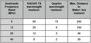
Objects that interact with or alter the response of the transmit or receive antenna can affect bearing accuracy or create bearing gaps in coverage. Position SeaSonde antenna one horizontal radar wavelength or greater away from tall (one quarter of the radar wavelength or taller) objects or obstructions (see chart). There should be no obstructions between the SeaSonde antenna and the seaward side that may block energy in direction of ocean. Ideally, position receive antenna one horizontal radar wavelength or greater away from a cliff or building edge (see chart). 5 MHz transmit and receive antenna should be spaced at least 50 m apart from each other.
Distance (on horizontal axis) from Water to Antenna
Antenna should be positioned close to the water to prevent propagation loss of energy traveling over ground. Maximum recommended distance from SeaSonde antenna to water is four radar wavelengths (see chart). |
| RADIAL SITE DATA ACQUISITION SYSTEM (SSDA 100) |
|
SSDA 101 Consists of:
Mini Computer + Monitor: color TFT + Keyboard & Mouse: USB, extended
Radial Suite Software License (online version, single-use) & USB Software Key
Temperature Range: 0° F (-18° C) to 90°F (32° C) for mini-style computer
Maximum Humidity: 80% non-condensing
Compatible Communications: 10/100/1000 Base-T Ethernet (RJ-45 connector) & Others (such as dial-up modem).
Communication Link Requirement
• A reliable data communications link is required for:
• Real-time data transmission,
• Real-time system monitoring,
• Proper system maintenance and customer support,
• Remote software updates.
• 1 Mb/s for optimal remote interactions.
|
Radial Suite Software
Data Products
Radial Surface Current Velocity Maps
Radial Map Display: archived ASCII vector files-- formatted to CODAR's LLUV columnar table format (MatLab® loadable).
Spatial Range (typical): 15-300 km offshore; 15-300 km alongshore. Observable range varies upon operating frequency, ocean conditions, external noise levels, antenna siting and a variety of other factors.
Range Resolution: user selectable from 200 m - 12 km. Resolution is based on transmit signal sweepwidth.
Angular Grid Spacing: 1-5 degree bins: user selectable.
Data Temporal Interval: User selectable in software. Typical averaging performed over one hour.
Current Accuracy: Varies with environment. Rms typical for the radial current speed: < 7 cm/s and 1-2 cm/sec for the tidal component.
Doppler Cross Spectra Binary files of HF sea echo spectra for three receive channels (two cross-loops & vertical element). Raw and averaged are available for processing into radial vector maps.
Range Processed Spectra (Range Series)
Optional binary files of receiver range processing which can be processed into Doppler cross spectra.
Raw I & Q voltages (Time Series)
Optional binary files of receiver analog measurements which can be processed into range spectra and Doppler cross spectra.
Wave Field & Wind Outputs
Local on-shore wave conditions and wind direction averaged in range rings around each radar. Measurement range cell user-selectable. Wave field parameter measurements do not extend as far as radial surface current measurements. Ability to obtain any wave information with an HF radar is limited and will vary based on operating frequency, ocean conditions, external noise levels, antenna siting and a variety of other factors.
Significant Waveheight. typical accuracy: 7-15%
Dominant on-shore Direction. typical accuracy: 5-12 degrees, depends on waveheight.
Dominant Wave Period. typical accuracy: 0.6 s
Minimum Detectable Significant Waveheight: 0.2-1.5 m minimum, this will vary based on operating frequency and ocean conditions.
Data Temporal Interval: User selectable. Typical and recommended wave averaging performed over one hour.
Wave History Displays: Hourly waveheight vs. time. Hourly wave direction vs. time. Hourly wave period vs. time. Wind direction vs. time.
Diagnostics
ASCII or image of diagnostic time series data for system hardware, software and data performance parameters. ASCII files are formatted to CODAR's columnar table format (MatLab® loadable). |
SeaSonde Radial Software
Properties & Functions:
• Real-time autonomous operation & processing of current and waves
• Radio call sign capability for adherence to ITU guidelines
• Real-time system monitoring, diagnostics, logging & alerts (via email)
• Hardware
• Temperatures
• Voltages
• Data Acquisition
• Miscellaneous Hardware
• Software
• Applications/Tools running (relaunch if not)
• Data collection & processing
operations
• Acquisition and archiving
• Configuration done via Graphical User Interface
• Layered configurable properties for both basic and advanced functions including waveform settings
• Graphical or command line control and monitoring
• Visualization Software for all stages of data (raw binary I & Q to vector maps) and diagnostics
• JPEG or PNG plot images for sharing via email or web publishing
• Data archiving utility
• External Antenna Response Calibration & Implementation
• Multiple levels of configurable Quality Control:
• Signal-To-Noise Computation &
Thresholding
• Peak Identification & Characterization
• Ship Echo Removal
• Burst Interference Removal (Lightning & Others)
• Ionospheric Noise Removal
• Outlier Detection & Removal
•Management for shared frequency, when using the SHARE technology
•Additional capabilities available with add-on software packages |
| |
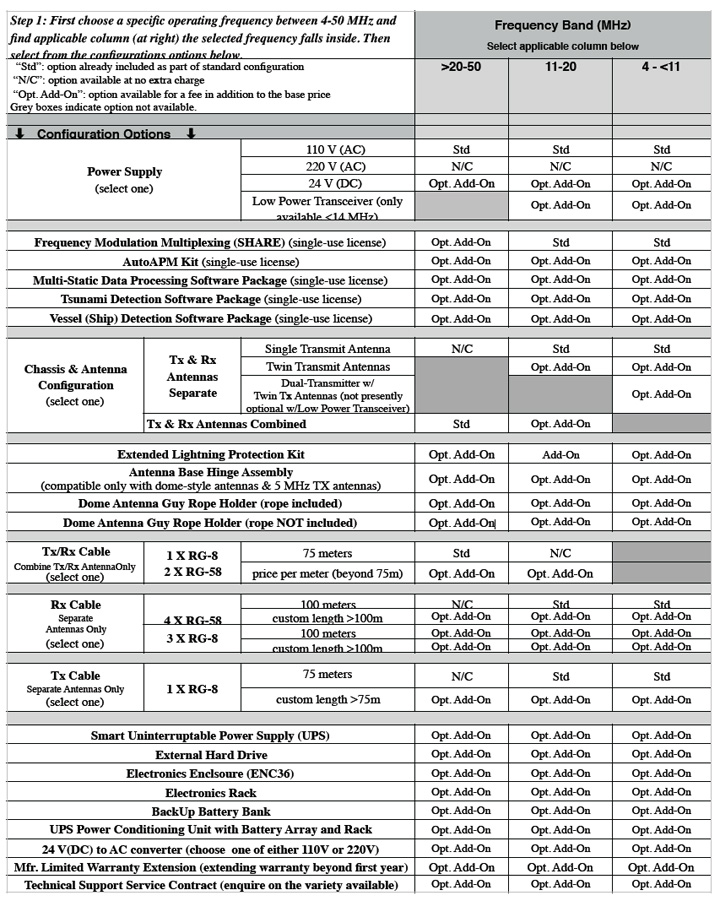
SeaSonde Remote Unit Configuration Option Guide
 |
SeaSonde Remote Unit Configuration Options Grid, v1, rev 12/2016 |
| |
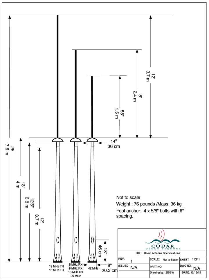
Anetenna Dimensions (examples of most common frequencies)
|
| |
 |
| |
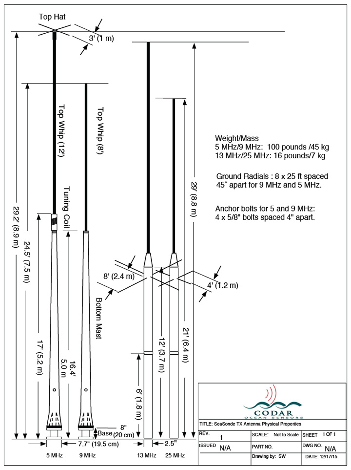
Transmit Only Anetenna Dimensions (examples of most common frequencies)
|
| |
 |
| |
SSRS-100 specification, v5, rev 12/2016 |
|
|
